DiProWIN
Easy-to-use CAD-CAM system that only Sodick could have made.
Main Features
- Operating Environment
- The cost performance of a CAD-CAM system is determined by the platform.
High performance DiProWIN is installed on a PC (*). It contributes to downsizing the office environment.
* Platform: DOS-V-compatible
Operating system: Windows10 (32-bit/64-bit), Windows11 - Support System
- A dedicated help desk is provided to support rapid startup after installation. Our specialist staff carefully handles all customer inquiries.
- Module Configuration
- Are you looking for a system like this?
- Part machining [CAD basic module]+[Wire CAM]+[Machining CAM]
- Die manufacture [CAD basic module]+[UNIT]+[Parametrics]+[Required modules]
- Electrical discharge system [CAD basic module]+[Electrical Discharge CAM]
Freely select the required DiPro modules to meet the requirements of the customer.
Of course, modules can be retrofitted after purchase.
CAD Functions
CAD Basic Functions
CAD Basic Functions
DiPro CAD is principally a die and mold design CAD with features that add applicable depth to machine weight as required by the situation while using the minimum number of operations.
● Never Get Lost on a Magnified Display
The range displayed on the editing screen can be constantly checked to specify the zoomed range.
● Parts Functions
By registering parts on a development view on a strip layout diagram, changes on one development view are synchronized in the development view of other stages.
As the dependency is the same between the development views, there is no need to be conscious of complex parent diagram/child diagram relationships.
● Picture Functions
Multiple pictures can be created in a single drawing file.
This is effective for the central management of assembly drawings and strip layout diagrams.
Each picture has 255 layers. Shapes can be copied and pasted between pictures.
Changes in part shapes are synchronized in development views on other pictures.
● Specify the Required Range and Paste Magnified Views of Detailed Areas
Of course, the scale is maintained after zooming.
● Draft and Solid Line Drawing Navigation Functions
The draft navigation functions switch the draft elements to lines and circles for more intuitive drawing creation.
Similarly, solid line drawing navigation functions are provided to create lines, arcs, and circles.
● Smart Placement of Dimension Lines
Move the cursor to select the dimension line direction as horizontal, vertical, or parallel.
Move the cursor to select the dimension line direction as horizontal, vertical, or parallel.
● Improved Text Functions
Easily place text using set phrases and special characters.
Flip/mirror texts can also be placed.
● Easy Layer Management
The layer diagram gives an overall understanding of the registered shapes. A single shape can be registered to multiple layers, which eliminates the need to copy the same shape for different machining processes and aims.
● Extracts Areas where Multiple Shapes Overlap. Only a single command is required.
● Customizable Menus
The screen menu layout can be easily changed and items added to suit the user's application.
● Machining Information Statistics Macro
Displays a list of machining information for each plate. (Figure 1)
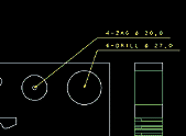
● Automatic Dimension Macro
Automatically inserts the dimensions for each plate after development. (Figure 2)
● Connecting Line Macro
Low-accuracy DXF data output by other CAD systems an be used in drawings. Elements not in contact with the end points are automatically searched within a preset range of tolerance values and connected together.
● Title Block
An original title block can be registered and pasted. The creator's name can be added, if required. (Figure 3)
● Functional Shape Macro
Special shapes can be created based on user-defined functions. (Figure 4 shows a rotary compressor.)
Press Die Design Support
Comprehensive functions are provided to support the detailed requirements for die design. The system provides sound support for the user's empirical rules.
● If the bending coefficient is specified, the neutral plane is calculated from the product cross-section to create the cross-section after development.
● Visual Confirmation of the Bending Process
Simulation of the processes is performed by specifying the bending angle for each process based on the developed shape.
● Optimum Yield Rates
The yield rate is calculated from various conditions required by the user, such as the bridge width, edge allowance, and material width. Naturally, the holes can be freely arranged at the appropriate positions while performing the simulation.
● Placement of the Cutter at Any Stage using the Set Feed Pitch
● Skeleton Diagram
Parametric, Gear, Cam Curves
● Simply Enter Dimension Values to Create Drawings of the Die Part Shapes
The parametric function displays the shapes of essential die parts, such as bolts, with the minimum input of dimension values. Both manufacturer's standard parts and user's proprietary parts can be registered.
<Supported Die/Mold Parts>
■Press dies
MISUMI Inc., SANSEI Co. Ltd.
■Molds
Futaba Corporation, MISUMI Inc., PUNCH INDUSTRY Co., Ltd., CHAMPION Industrial Co., Ltd.,
Ikegami Mold Engineering Co., Ltd., Japan Die & Mold Industry Co., Ltd.
● Creates Gear Shape Drawings with the Minimum Input of Values.
Supports both total and partial gear shapes.
Select the method to determine the addendum modification coefficient from the following options.
・number of teeth in the span, base tangent length
・Over-pin diameter, over-pin dimensions (external teeth)
・Between pins diameter
・Between pins dimension (inner teeth)
・Arc tooth thickness
Handles the tooth trochoid when an undercut occurs.

● Permits Fine Tooth Face Corrections
The special involute gear functions support fine curve corrections of the tooth profile that are not supported by standard tooth profiles, such as shrinkage during forming. They can create drawings incorporating different addendum modifications and missing teeth within a single gear.
● Select from the Following Cam Curve Types
constant acceleration cam/modified constant acceleration cam/harmonic cam/trapezoidal cam/modified trapezoidal cam/cycloid (Bestehorn)/modified sinusoidal cam
● Creates Timing Diagram and Cam Roller Center Path Diagram from the Angle, Roller Diameter, and Type of Cam Curve
Die/Mold Structural Design Support
The end result is a culmination of the knowledge and skills that DiPro possesses. Automated procedures and individual user settings are fused in perfect balance.
● Achieves Substantial Lead Time Reduction for Designing
Comprehensive parameters encompass the die structure of the plate, part holes and the part. They can be reused to standardize the design, reduce time, and communicate the intentions of the design and manufacturing sites.
● Simple Parameter Definitions for Die Manufacturing Registration
Easily accommodates both manufacturer's standard parts and user-defined structures.
● Information Can be Registered for Each Part Hole Type
The essential information for hole machining, such as the machining method, radius, and depth, can be defined by simple parameter inputs.
● Typical Manufacturers' Mold Bases can be Placed Simply by Entering the Mold Number
Supported manufacturers: Futaba Corporation, Japan Die & Mold Industry Co., Ltd.
● Linking of Die/Molded Plate Part Holes and the Part Diagram
When designing part holes and punch shanks, etc., the part diagram is positioned at the same time as the holes.
Moreover, when the hole dimensions or cutter shape are changed, the part diagram and hole modifications are synchronized.
● Drawings of the clearances and trap holes are created automatically by clicking on the shape.
This eliminates the need for tedious manual editing of each part hole.
● Checks if Water Tubes are Placed Correctly
All plates are checked. If any position is discovered where the water tubes interfere with other part holes, the corresponding plate is displayed.
● Automatic Following of Hole Positions
As the positional relationship is maintained between the plate and part holes, the part holes are rearranged in the correct positions when the plate size is changed.
No tedious rearrangement is required due to a change in size.
● Automatic Following of Counter bore Depth
The plate size includes the thickness, in addition to the width and height. As well as through-holes, the system also supports holes with specified depth with reference to the upper surface or with specified residual depth after counter boring. The part holes are rearranged in the correct positions when the plate thickness is changed.
● Support for Splitting Insert Dies
Easily handles insert dies that are introduced due to die design changes.
Insert dies can be handled the same as other plates as there are holes already provided and there is no need to regenerate graphics/information for insert dies themselves as separate plates.
● Part Table Output
Automatically creates he important documents required for management to prevent mistakes in ordering.
● Development Each Plate
The machined shaped of each plate can be developed from the plate structure. As the machining information is retained for each plate, subsequently only the NC programs are output by the CAM.
CAM Functions
Wire CAM
This is a respected system in the machine shop. It incorporates considerable Sodick wire electrical discharge machining expertise. It creates NC programs for complex shapes with the minimum number of operations.
● Comprehensive Machining Parameters Available Can be freely combined as you require.
Coreless machining
Machining with different upper and lower shapes
Taper machining (full/partial)
Die, punch, open machining
Numerous machining patterns can be freely combined to suit the machining process
● DiPro Coreless Machining Leaves No Residue
Spiral machining similar to pocket milling leaves no core. DiProWIN coreless machining offers proprietary corner machining that leaves no residue.
● Path Shapes Supporting Corner Relief Created Separately for Roughing 1st and Finishing
● Select the Required Approach
Numerous types of approaches are provided that affect the machining efficiency.
(From left to right: straight line, arc 1, arc 2, end point, special, cut out)
● Smooth Process Management
Calculates the machining circumference and accumulated machining time required for process management from the detailed processes.
● No Manual Editing Required at the NC Code Level
The flexible postprocessor outputs NC programs compatible with all types of wire-cut EDMs.
● Improved Standardization of Machining Methods
Accumulated user know-how about numerous parameters for machining definitions, machining processes, machine information, and machining conditions contributes to standardization of the machining methods.
● Automatic Checking of Taper Interference
Provides reliable checking of taper interference that is hard to evaluate visually.
● Real-time Checking of the Wire Trajectory
Projection images offer three-dimensional observations of the inclination of the wire, which is difficult to grasp from plane images.
(The diagram shows machining of a screw with different upper and lower shapes.)
● Automatic Selection of Optimal Machining Conditions
Automatically select the optimal machining conditions, with minimal input. The user can add or edit these machining conditions.
Machining CAM
This provides a powerful tool for shape machining. A 2D system can also accomplish this.
● More than a simple check of the tool effective length.
Checks the effective length of the tool used and indicates the appropriate remedy when the effective length is too short.
● Eliminates Waste in Step Machining
Specifying the step depth eliminates the waste of air cuts in the step.
● Saves Tool Motions
It is not possible to visually follow tool trajectories that include depth. When outputting the NC program, the tool trajectory simulation ensures there are no errors in the run-on directions or hole boring sequence.
● Efficient Tool Replacement Setting
The tool seizure time can be set from the number of machined holes and the cutting circumference. A substitute tool can be specified at the set time to ensure efficient tool replacement and stable quality.
● No Need to Separately Create the Front and Rear of Plates
Sets the conditions for machining the front and rear surfaces for a single plate drawing.
● No Need to Revise Drawings due to Quenching Contraction
Performs machining with hole positions that anticipate the quenching contraction.
● Smooth Process Management
Calculates the machining time as information required for process management from the detailed processes.
● No Manual Editing Required at the NC Code Level
The flexible postprocessor outputs NC programs compatible with all types of machining center (NC milling machine).
● Improved Standardization of Machining Methods
Accumulated user know-how about numerous parameters for tool information, cutting conditions, machining processes, machine information, and magazine information contributes to standardization of the machining methods.
● Inclined Machining With Area Machining is Added
● Diverse Cutting Methods Available
Boring functions: drilling, reaming, tapping, chamfering, etc.
2D pocket machining: contouring, area machining, embossing, etc.
2.5D machining (wire frame):contouring, area machining, embossing, pocketing, sweep machining, lead machining, offset machining, revolved sectioning, etc.
Electrical Discharge CAM
Dynamic uniform management from creating the electrodes to electrical discharge machining. This is the key to reducing lead time.
● No Special Preparations Required
Workpiece and electrode drawings can be directly reused.
The only preparation would be deleting shapes that require no dimensions.
● Easily Determine Measurement Points
Easily Determine Measurement Points
● Standardization from Workpiece Layout
Accumulated user know-how about numerous parameters contributes to standardization of the machining methods and machining conditions.
● Dramatically Enhances the Utilization Rate of EDM
Covers all NC programs from workpiece positioning to electrode centering and machining programs to reduce the machining tool setup time and improve the utilization rate.
● Ripple Effect
Handling workpiece positioning and electrode centering by CAM eliminates the specialization required by the technician to set up the machine tool and reduces the training period of the operator. Moreover, it provides a bridge to EDM automation systems.