- Language:
- JPJapanese
- ENEnglish
- CNChinese
-


- 8


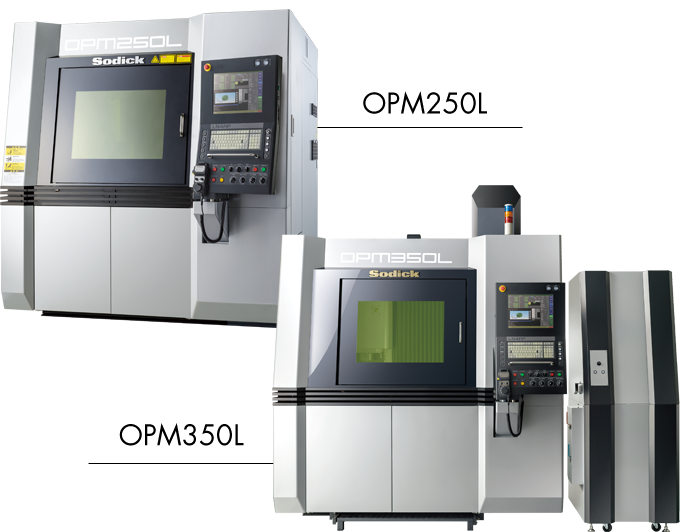

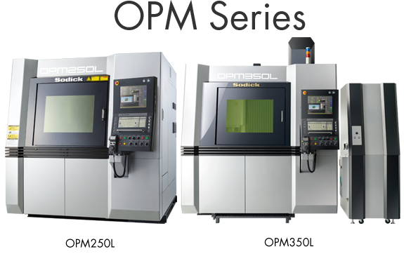
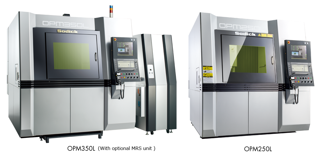
OPM350L/OPM250L
The Sodick “OPM Series” OPM250L and OPM 350L precision metal 3D printers are an innovative manufacturing system capable of producing one-piece metal molds, fundamentally changing how molds for plastic products are created.
With enhanced productivity, reduced lead times, and substantial cost reduction for molded products, the system achieves levels of performance not possible on conventional production systems.
Moreover, the OPM250L and the OPM350L come prepared for integration with the Internet of Things (IoT) to allow unmanned and automated production at the manufacturing site. Designed to permit remote operation, the system significantly reduces labor costs by streamlining the production process.
Sodick Group is committed to expanding its core technologies for all processes to offer one-stop solutions, following our tradition of “Creating What We Cannot Find in the World.”

Sodick proudly introduces practical one-stop metal 3D printing solutions.
An one-stop solution of
a practicing precision metal 3D printer is proposed.
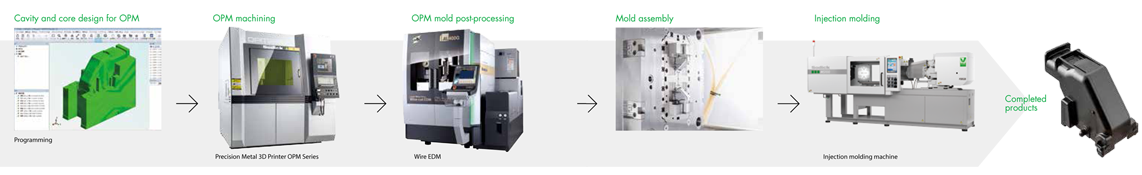
The OPM Series precision metal 3D printers allow us to offer an industry-leading “onestop solution.”
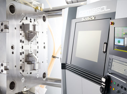
Sodick provides integrated support for all processes, from design to molding, through its extensive technologies, including wire-cut electrical discharge machines, die-sinker electrical discharge machines, injection molding machines, and machining centers.
Performing laser sintering and high-speed milling on the same machine permits the machining of complex molds with a degree of freedom and high-precision finishing that is simply impossible with conventional cutting tools.
The OPM Series performs continuous laser machining and high-speed milling in a single machine.A uniform layer of metal powder is melted and solidified through direct metal laser sintering.
Thisis then precision machined by high-speed milling to create a high-quality shape not attainable through additive manufacturing alone.
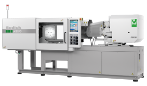
Sodick employs the V-LINE® system that separates the plasticization and injection processes. Adopting the proprietary V-LINE® system allows the development of a zero-backflow system. After weighing, the flowis actively cut off before the injection operation is performed, so that all weighed resin is injected into the mold. The introduction of the V-LINE® system brings about accurate filling volumes for more stable molding.
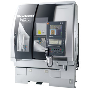
In addition to our proven linear motor and high-speed milling technologies, the UH Series offers practical machining simulation software and an ergonomic, curved design. Through full linear motor operation, Sodick machining centers achieve high-speed, highprecision, high-quality machining.
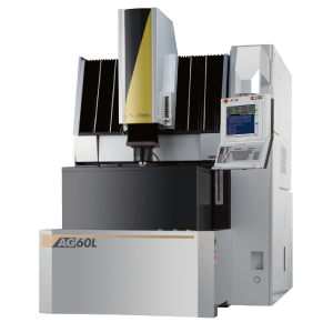
The new “Arc-less Plus” electrical discharge machining system is installed standard, lowering overall costs and human errors by substantially shortening machining times and reducing the number of electrodes required. Moreover, the SVC circuit rapidly creates high- quality satin or mirror surfaces.
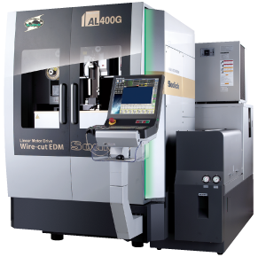
Smart Pulse electrical discharge technology and a proprietary direct tension servo mechanism accomplish both high-speed and high-precision machining for unparalleled performance. Additionally, the FJ-AWT high-speed automatic wire threader incorporates a wire straightening function, enabling high wire threading rates.
The result is reduced work hours and long-term, unmanned operation.

Additive Manufacturing with Sodick’s precision Metal 3D Printer
The OPM Series is an automated machine that melts and solidifies a uniform layer of metal powder in a process called laser sintering. The machines then engage in high-speed milling for highly accurate finishing. Sodick proudly achieves metal 3D printing through the use of a 500W fiber laser for the melting and solidifying metal powder.
The OPM Series features a 45000 min-1 spindle that achieves high-speed and high-precision machining with Sodick’s non-contact rigid linear motor drives.
An automatic tool changer (ATC) and automatic tool length measuring device are installed to allow continuous automated operation over a long period of time.
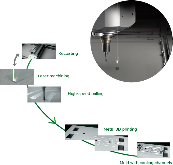
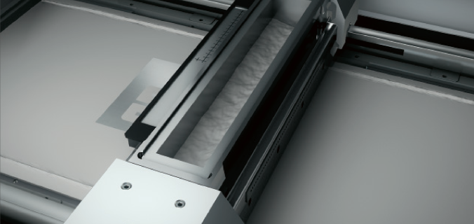
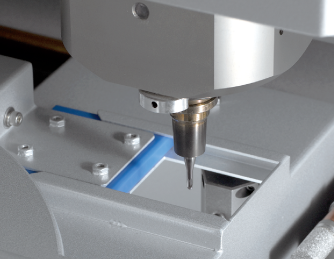
Recoating
After each layer is fully machined, the workspace is recoated with metal powder and the process is repeated.
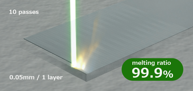
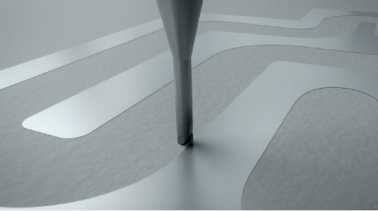
Laser machining
Milling is performed after 10 laser machining operations. These processes are repeated to perform 3D printing (additive manufacturing) of the workpiece.
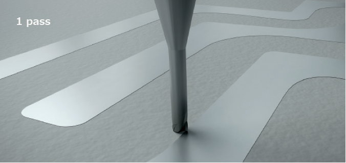
High-speed milling
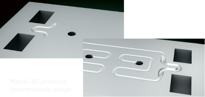
Metal 3D printing
Mold with cooling channels

Sodick In-house Developed and Manufactured New NC Unit and OS-FLASH Dedicated CAM
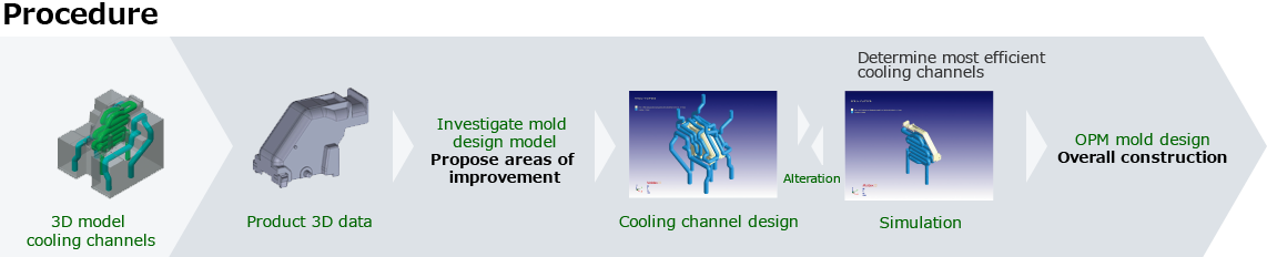
After designing a mold with 3D cooling channels using CAD software, a plastic temperature simulation is performed using CAE. Next, the optimized 3D CAD data is loaded into the "OS-FLASH" dedicated CAM system, which creates the NC program and directly supplies it to the LN4RP NC unit.
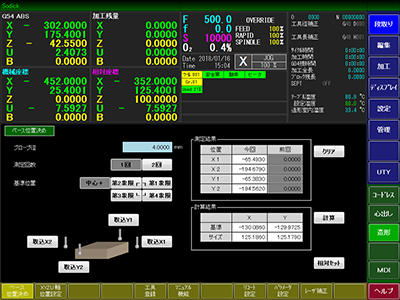
Easily configure the settings before mold manufacturing. Production data can be imported by simple drag and drop procedure.
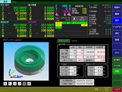
Shows laser machining progress at a glance.
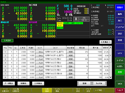
Acquires tool information from CAM and displays the settings and tool use status.
Accurately controls the linear motor’s precision movements according to commands from the NC unit. The K-SMC motion controllers designed and manufactured by Sodick ensure reliable control for high speed, high acceleration, and accurate positioning.
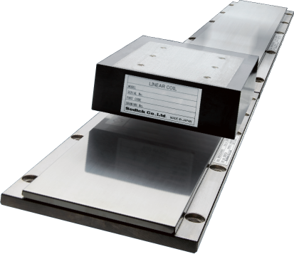
Sodick employs high-performance linear motors developed and manufactured by Sodick, replacing ball screw drives with a reliable direct drive system.
These linear motors indefinitely maintain backlash-free, accurate axis movements, which is impossible with conventional ball screw drive systems.
A space-saving machine layout design is achieved by arranging the drive axes for high-speed milling and laser machining in a compact structure.
Sodick has fostered a line of high-speed, high-accuracy cutting technology over the years using high-speed milling center developed in-house. The OPM Series permits stable finishing for a wide range of applications by integrating proven machining expertise with this high-speed milling center.
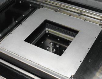
Sodick is an expert in vacuum chamber design, with over 10 years of production experience.
First designed in 2003, Sodick’s vacuum chamber technology has been tested in the PF00A/PF32A Electron Beam PIKA Finish EBM, with great success. By maintaining a high concentration of inert gas, Sodick’s vacuum chamber achieves stable and accurate laser sintering.
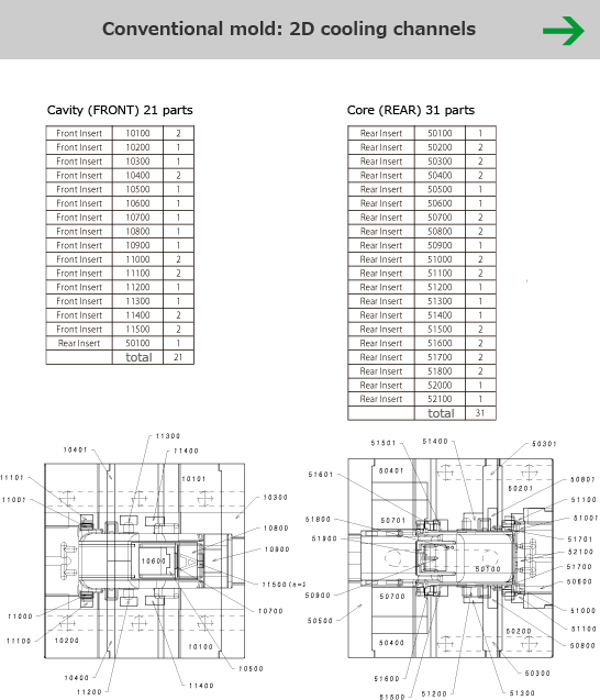
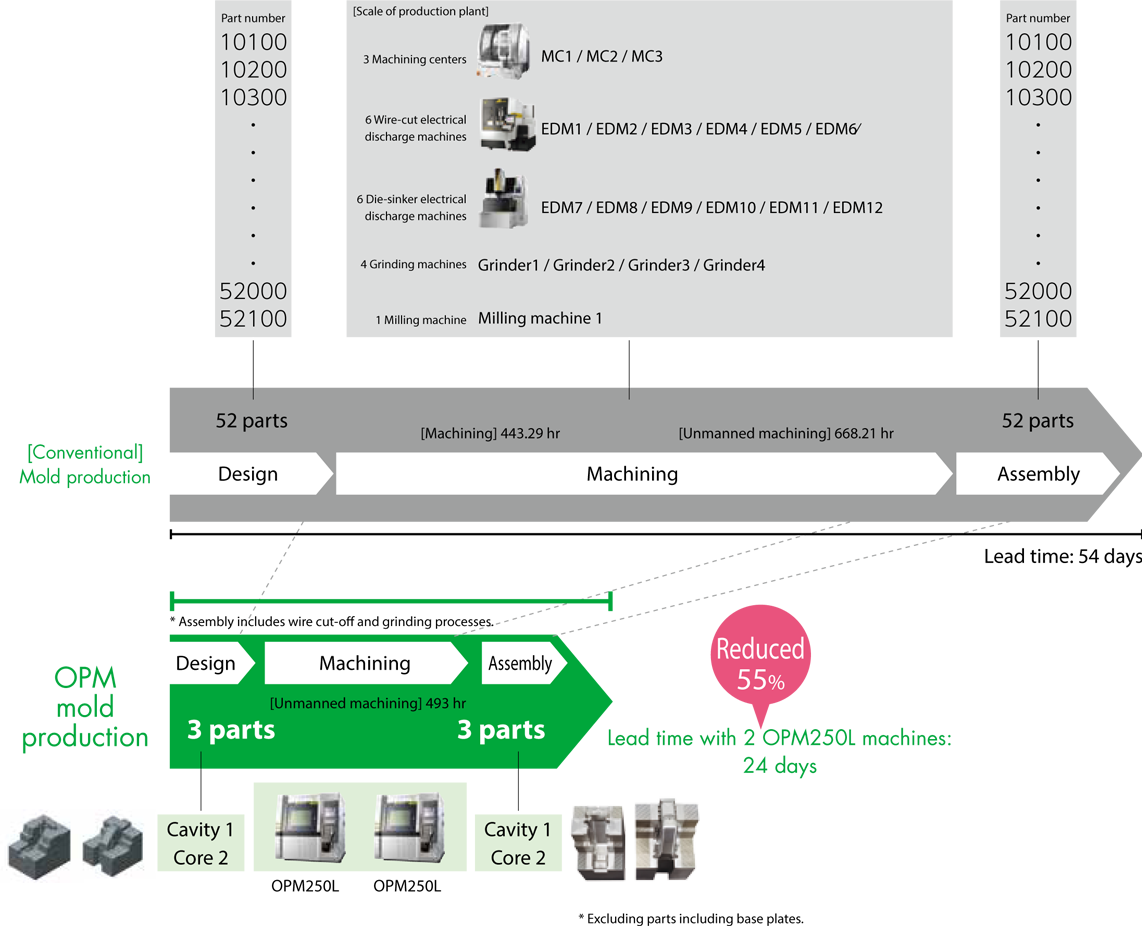
The expertise of experienced engineers was indispensable for conventional mold manufacturing, which required complex processes, numerous parts, and multiple machine tools.
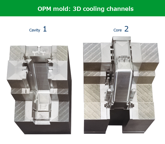
Today, however, the OPM Series may be the only machines that encompasses a full production system to manufacture high-density, finished molds with one-piece construction.
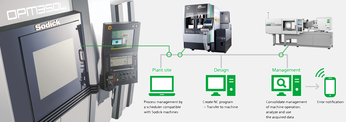
With high-quality mold data, the OPM Series allows for unmanned manufacture of highquality molds anywhere. It is easy to create a “Mold Internet of Things” to control production from a remote design department.
The result is automation with reduced lead times, lower costs, and significant labor savings. In this way, the manufacture of uniform quality products in any location can be achieved.
Sodick NC units apply the following security measures to the network connections.
LN4RP power supplies offer :
• System protection with the FBWF (File-Based Write Filter) function
• Prohibited execution of files other than CNC system files;
• Data communication between power supply and external PC using FTP;
• Prohibits connections, except to Sodick-certified USB memory
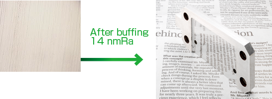
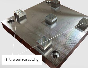
Mold manufacture requires a high sintered density (99.9% melting ratio) and highly accurate machining. The OPM Series meets both criteria, permitting finishing (SPI-A2 class) not possible with a conventional metal 3D printer.
Required precision of ±1/100 mm in maraging steel All shapes were achieved.
When plastic products are injection molded, the molding performance is significantly affected by the construction of the mold used.
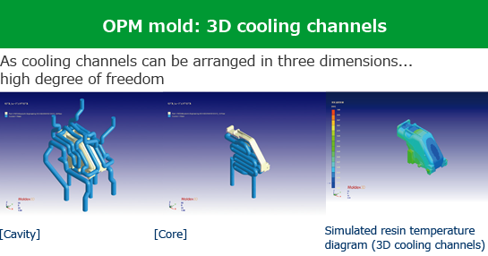
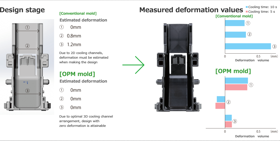
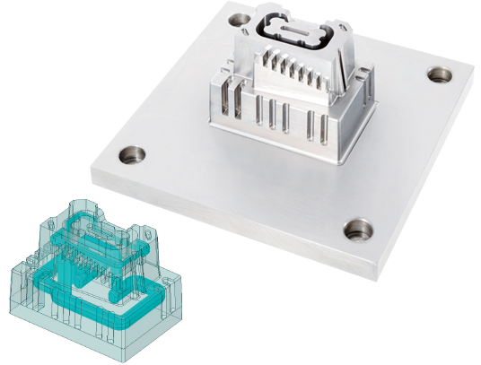
Temperature control inside the mold is always a critical element in this aspect.The OPM Series can produce molds with 3D cooling channels freely positioned inside, eliminating uneven temperatures within the mold.
It allows an ultra-high cycle rate that was impossible with a conventional mold and permits optimization of the molding shrinkage. As a bonus, these process improvements reduce the lead time by half or more.
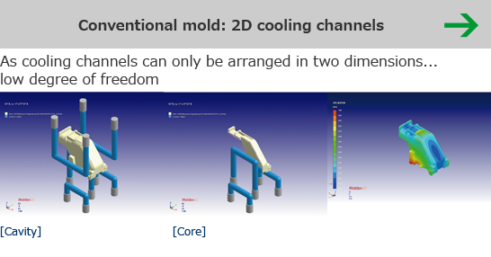
Moldex3D plastic injection molding simulation software (Core Tech System Co., Ltd.) permits the 3D arrangement of cooling channels which can normally be arranged in two dimensions only. It also performs simulation of molded products during injection molding.
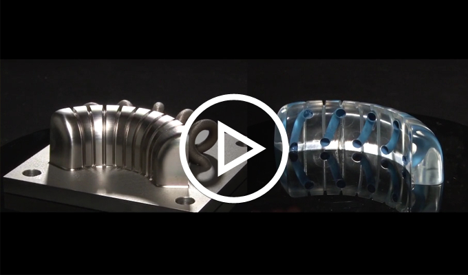
Side-by-side comparisons with conventional molds confirm that deformation is lower with the 3D cooling channels.
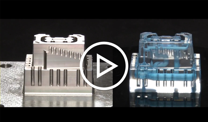
Suppresses the deformation of the molded products by allowing conventional split molds to be made as one piece, achieving an optimal cooling channel arrangement that was not possible with conventional machine tools.

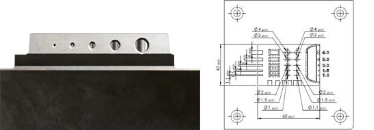
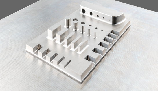
To improve cooling around the central ribs, the cooling channels are arranged to surround these areas.
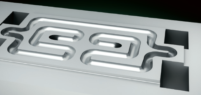
The interior of the cooling channels are machined to enhance surface roughness and an adequate volume of cooling medium flows through the 1.2 mm diameter channels. All machining can be performed by a single process on the OPM250L, including the many ribs arranged around the perimeter.
DATA
Machine used: OPM250L
Mold manufacturing (sintering) time: 15 hr
Cutting time: 28 hr
Total time: 43 hr
Mold size: 60 mm × 40 mm × 40 mm
Material: Maraging steel
Tools: 1 and 2 mm dia. ball end mills
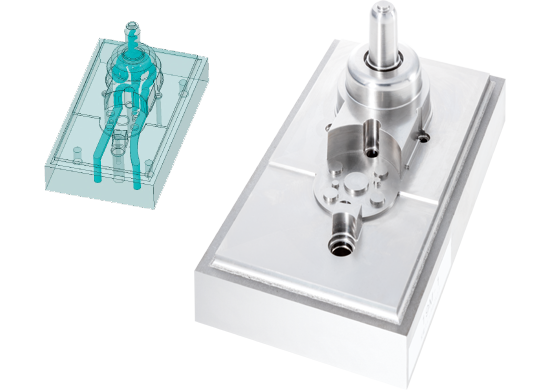
A spiral cooling channel is placed in the difficult-to-cool protrusion in order to achieve higher cooling efficiency than normal spray or baffle cooling.
Additionally, a peripheral cooling channel that uniformly cools the molded product restricts the deformation of the plastic molded product.
DATA
Machine used: OPM250L
Mold manufacturing (sintering) time: 17 hr
Cutting time: 25 hr
Total time: 42 hr
Mold size: 120 mm × 70 mm × 73 mm (including the plate size)
Material: Maraging steel
Tools: 1 and 2 mm dia. ball end mills, 1 mm dia. flat end mill
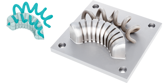
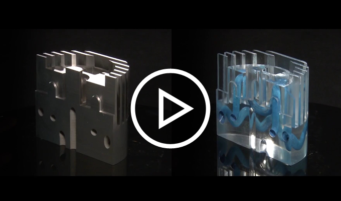
The OPM Series permits the design of spiral cooling channels inside a curved shape, which is impossible to machine with general machine tools. High-precision processing of external shapes, including deep ribs, and machining of the internal spiral structure can be handled on a single machine.
DATA
Machine used: OPM250L
Mold manufacturing (sintering) time: 16 hr
Cutting time: 43 hr
Total time: 59 hr
Mold size: 92.1 mm × 36.3 mm × 33 mm
Material: Maraging steel
Tools: 1 and 2 mm dia. ball end mills
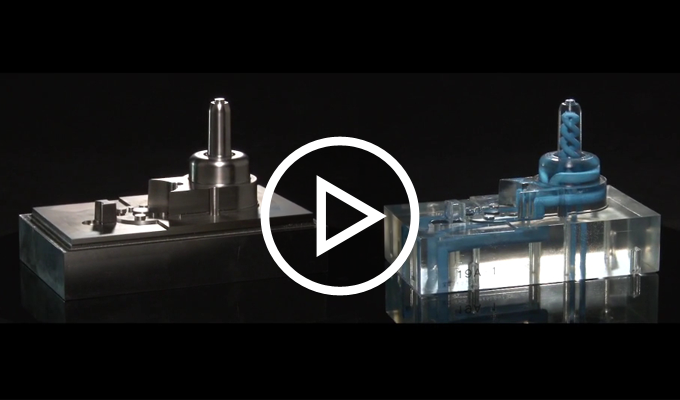
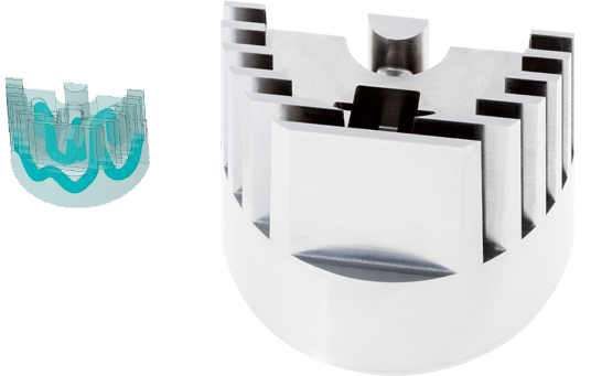
Adequate cooling channels can be designed at the center of a cylinder surrounded by deep ribs to achieve a high cooling effect at the tips. The multiple ribs can only be finished by the OPM250L, which significantly cuts the number of machining processes.
DATA
Machine used: OPM250L
Mold manufacturing (sintering) time: 29 hr
Cutting time: 67 hr
Total time: 96 hr
Mold size: 79.6 mm × 39.8 mm × 61 mm
Material: Maraging steel
Tools: 1 and 2 mm dia. ball end mills, 1 and 4 mm dia. flat end mills
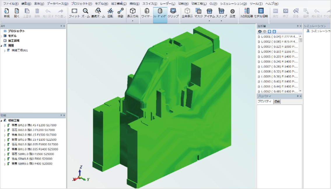
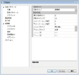
Specialized parameter settings for compound machining
CAD interface
Cutting data
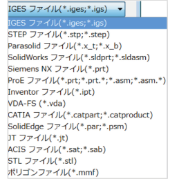
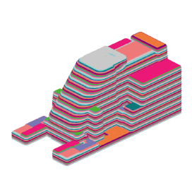
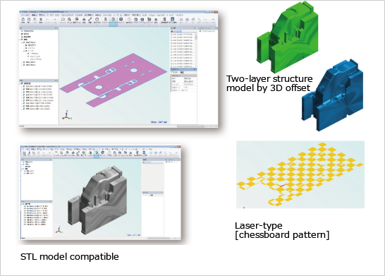
By applying a 3D offset to the input 3D model, various laser data can be created, such as the two-layer structure consisting of melt parts and core parts, as well as sintering methods that create a chessboard pattern. Laser data can also be created for the STL file, allowing for the manufacture of scanned data.
Sophisticated and rapid editing can be performed to optimize the cutting data and reduce the cutting time and cutting loads.
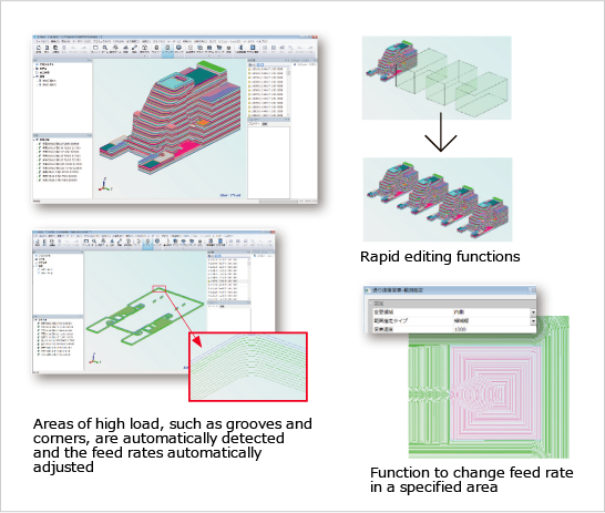
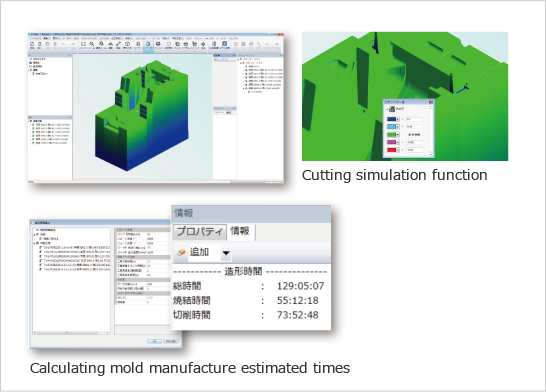
The cutting simulation function can be used to confirm unmachined and excessively cut sections. The mold manufacturing time calculation function calculates times by considering the movements of the machine to allow appropriate process management.
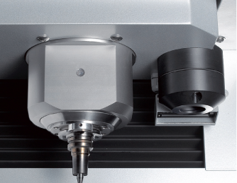
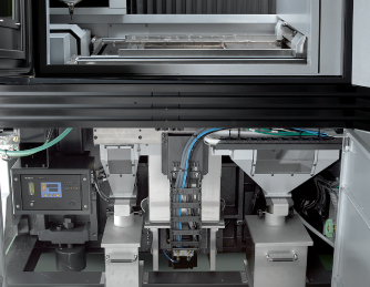
Features a 45000 min-1 spindle for high-speed milling.A CCD camera is used for laser positional correction.
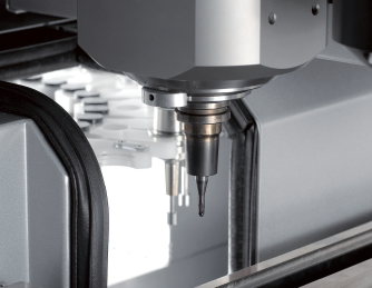
A device that automates the exchange of tools between the spindle and magazine. Up to 16 tools can be set in the magazine. (* Up to 20 tools for OPM350L)
Device to measure the distance between the spindle reference plane and tool tip.
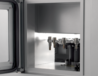
The area where the tools are set in the automatic tool changer (ATC) magazine.
Supplies nitrogen gas to the machining area.
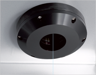
Provides laser irradiation to sinter the metal powder.
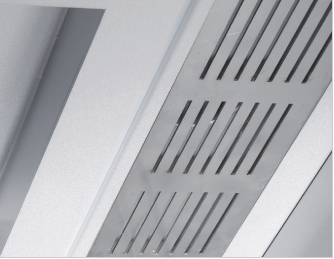
Exhaust port for the machining area.
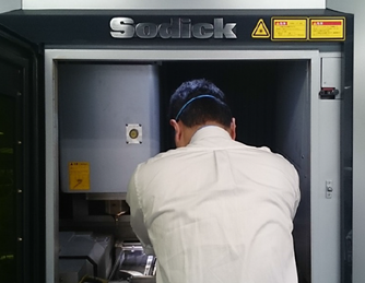
By adopting the wide-open operation door, both presetting before forming and after-maintenance becomes easy.
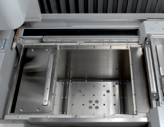
Offers mechanisms to secure the base plate for laser sintering and set the base plate to the required height.
Mechanism to restrict the recoated area when the mold has a small surface area (optional).
* Conceptual diagram
Automatic compensation that measures and identifies alignment errors/positional deviations of the laser and the main spindle during machining.
Receptacle that recovers unused material after machining is complete.